Drillhole Planning For Mineral Exploration & 3D Modeling
Planning a drillhole, or creating a drilling program by bringing all of these plans together is the most decisive task of mineral exploration activities. The necessity of creating a drilling plan arises at the onset of exploration, persisting throughout the operation, whether it involves mine development or project expansion. You need a plan to carry out drilling activities from any point on the surface, underground, open pit slopes, above stakes, anywhere you can think of. The “core information”, which is the data you will obtain from drillings, is more than what you can obtain from a wheathered outcrop you see on the surface while walking around the field. Therefore, we can say that drilling is creating an outcrop at the point we want deep underground. In summary, if we need information at certain points in order to produce or create a model to represent the ore body, we need to make the best drilling plan to obtain it.
Drilling activities, which are continuous throughout the exploration process, require constant monitoring and control. Remember that you will achieve the highest efficiency from your drilling activities if you dynamically compare your tracking and drilling records throughout the process. Because the drillholes you plan will not always intercept the ore in the meters you expect. Therefore, if you encounter a situation other than what you expected, it means that there have been deep structural changes in the ore you observed above.
Over millions of years, minerals in certain regions of the Earth have undergone enrichment, subjected to various surface and underground processes until the present day, when drilling occurs. Over millions of years, minerals in certain regions of the Earth have undergone enrichment, subjected to various surface and underground processes until the present day, when drilling occurs. Faulting and superficial weathering are the most commonly observed forms of these. No matter which type of ore model you have adopted with your studies before the drilling planning stage, a part of your concept will have been eroded – transported and its body will have been slipped laterally / vertically by a fault. As a result, that large ore body turns into a kind of puzzle underground. Catching and evaluating clues requires experience and knowledge. Although sometimes the luck factor overrides all technique; As in every stage of mining activities, “purpose” is always important, conscious steps will definitely lead you to success in what you want. Now let’s follow how to make a step-by-step “drillhole planning” below.
Additionally, you can explore the related articles listed below.
Preliminary Studies in the Office

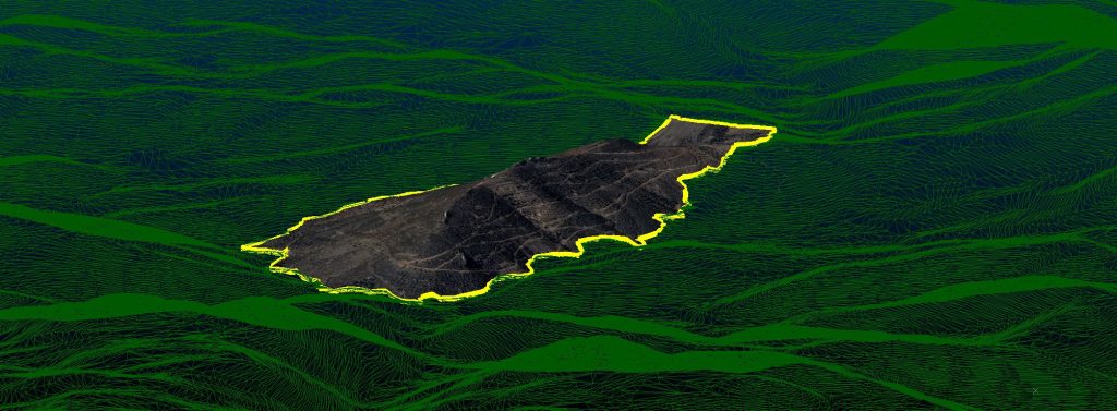
Whatever the size of your mineralization, purchase at least one of the 3D design programs that are no longer considered a luxury and start with a short training for your geologists. In the past, survey teams would scan kilometers of rugged terrain with GPS and digitalize the topography over months of work. It is extremely important that you obtain the “Digital Terrain Model” (DTM), the good news is that we can solve this with a few hours of drone work, plus a most up-to-date aerial photography. This digital terrain model allows our drilling locations to be in rocky area, wooded area, loam/mud etc. It will be very helpful to see if it comes across unsuitable terrain. Although we can see mid-detail aerial photographs in free software such as Google Earth Pro, unfortunately the elevation detail may not always be sufficient for us to decide on the drilling plan location. However, satellite data can be used if we have to.
What We Need to Do in the Field Before Planning Drillholes
Seeing the entire project in its entirety and making a decision can only be done on a computer. We can also describe this as “seeing the big picture”. Wait for the results of all the samples you took from the field to arrive, and after examine your systematic samples, such as soil samplings, in detail on the histogram and decide on the “anomaly” grade ranges to make them thematic in the most accurate way. If you can get a direction with this method, this is an advantage, we hope the sampling has been performed properly. If your ore body or a part of it is observed in the outcrop/outcrop, conduct line sampling in the steepest (Azimuth) sections possible, and if possible, take directional slope measurements and add them to your digital project design.
If ore body is not observed on the outcrop or subsides under cover after a certain outcrop appearance, measure the surface signs or all structural elements and add them to your digital project design. In addition to your geological mapping, examine the areas you expect on your design screen by superimposing the structural and alteration maps. The aim is to discover trend directions. If you have the opportunity to use geophysics, you can decide which methods to use and in which direction, taking into account the depth of mineralization you expect. It is quite possible that it will be beneficial according to the topography and mineralization details. It is essential that geophysical method and line directions are decided and approved by a geologist who knows all your project data and is familiar with your field. The same geologist should interpret the study results and identify trend directions and be the decision maker in drillhole planning.

Determination of Drilling Locations and Transportation Routes
We aim to ensure that the drillholes enter ore body as vertically as possible at every step, as conditions in the field allow, so we will choose our locations accordingly. You can proceed either by returning from the points on the ore body (Ore entry points) in the next step, or by selecting the locations first in this step.
You should make decisions on issues that require coordination such as your environmental sensitivity, local people’s consent, seasonal ground conditions, institutional or individual rents, and so on, and create your drillhole bases and routes in the digital environment. Let’s consider it item by item.
Place the square-shaped areas as bird’s-eye view of 10m x 10m (100 square meters), where we will deploy our drillings, on your aerial photographs and 3D topography and put a dot in each of these squares (Drillhole collars/starting points). Or, if you are going to drill underground, examine the gallery offsets (gallery/production maps) and place drilling starting points in available areas.
You can meet the water needs for drilling by transporting it by hose or tanker, as the topography allows. Of course, after determining your water source and contacting the relevant people in order to reduce the workload, you should make road planning to connect residential areas and surrounding roads to your locations.
In the next step, after creating target points on the ore body, you can optimize your number of drilling locations. Depending on its underground location, try to plan at least 3 drillings from each location, if possible, especially for the shallow parts of the mineralization. Considering that we can obtain a 3-dimensional area with at least 3 points, by extending these areas, we can predict changing ore body strike-slopes or fault slips in between underground and improve subsequent drilling plans. Although it reduces our advantage in terms of our goal of intersecting the ore body as vertically as possible, having the machine drill more than once in the same location means being advantageous in terms of both the time spent on deploying and getting to know the ground to be passed first. We may also take into account the rent and rehabilitation expenses payable for each location.
When you have completed all the drillhole plans and there is no location left to add or remove; After your “Drilling Program” is ready, you can go back to this step and have the necessary permit applications or field arrangements made for your drilling locations.
Creating Target Points on the Orebody
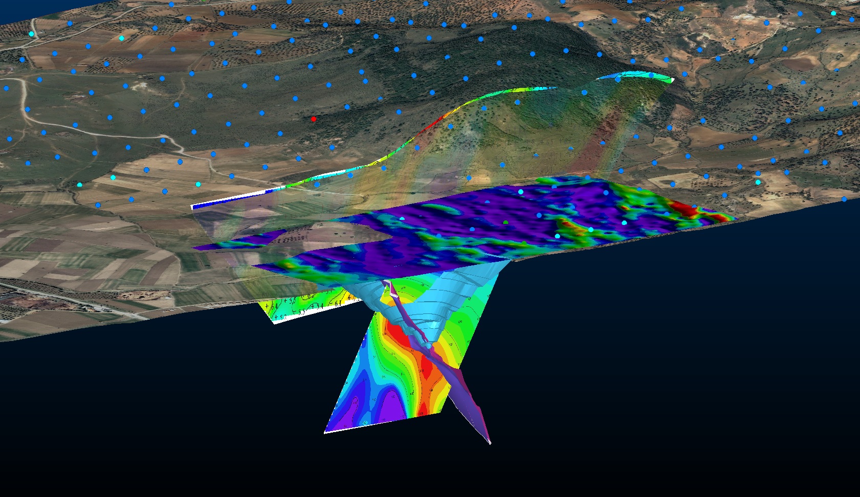
Save the overall ore body direction/azimuth, slope direction and slope angle (inclination) that you determined with the data you obtained in the field or underground as a 3D plate in a digital environment as a wireframe. Although creating a plate is sufficient, if possible, try to create a 3D solid model by incorporating your concept into the design in detail. Likewise, save the wireframes of the estimated fault planes that are under cover in the topography or observed on the surface and examine them on the same screen together with all project data. In the first place, your expectation should be to clarify the mineralization direction and cut the grade. Do not plan drilling near the intersection plane of the estimated faults that will make possibly slips around your mineralization. As an answer to the question “How close should we plan?”, you can consider more than half of your average drilling intervals as minimum. Faults will include torsion and discontinuity factors, as well as slips, in your planning at the point where they cut mineralization. In this way, even if your drillholes intersect ore body, it may cause you to be misdirected regarding the total mass direction. It is also possible that your drilling will coincide with the discontinuity gap caused by the fault.
You need to make a kind of grid (circular rather than square, even ellipsoidal as a result) on the 3D plate (Wireframe/solid model) you have obtained to represent your mineralization. Your drillings need to drill the center points (Ore entry points) of the areas you created with this grid. Your drilling frequency should be optimum; more than one drilling should be included within your screening ellipsoid dimensions for each block during block model grade estimation. Assuming your ore body is horizontal (inclination <20°), no matter what direction and slope it is, when you look at this horizontal plane as the crow flies, the points where your drillings should pass will be the centers of intersecting circles of a certain diameter (the points where the drillings should hit), leaving no empty space in between. Many experimental factors such as the continuity, consistency and mineralization dimensions you obtain from the ore body at different points will be decisive in determining the optimum value of the diameter you have determined. However, to give an example, for modeling the mass of an anisotrope hydrothermal mineralization with a length of approximately 1 km and an altitude of 300 meters on a certain confidence level, the optimum drilling distance on a continuous plate of 25 meters can be considered an average for the “determined (Rescat 2)” resource calculation. If there is no ore underground that you can track in the field or obtained through old drillings, it would be more correct to start by making exploration drillings with optimum 80 – 100 meter intervals, and then fill in the intervals (infill drilling) with drillings, reducing the intervals to 25 meters for the ore characteristics given in the example. Naturally, you will need to fill in the gaps in certain sections in your future projects or during the operational phase.
Do not expect a systematic or general acceptance at these stages; experts familiar with the structural elements will decide on the necessary drillings at the most optimum interval in line with your needs. Do not forget that consulting the expert who will create and/or report your ore model will prevent adding a drilling plan or extracting data later, because the interpretation of the geologist who will do the modeling is essential, going with a program from the beginning will definitely healtier.

Completing Drillhole Planning
If you are just starting the project, the most valuable parts of the ore body should be your first targets, with simple logic. We can clarify the slope direction of the ore body in your target area, which you have gradually narrowed down as much as possible with your large-scale studies, and place our drilling locations on the slope direction of the strike line. If you already have an ongoing project, you can place points that will fill large drilling gaps on the ore plate of your 3D project. In addition, by taking into account the plan quantity and ground characteristics, do not forget to determine the drillholes core diameters according to the lenghts and ground types which you start the hole, and then share it with your driller or the relevant company when sharing the program.
Let’s sum up,
- You have created the points that you think are suitable on the ore body (Ore entry points),
- Now connect these points with the points within the drilling locations you created (Drilling starting points) and extend the lines (strings) in the same direction at a considerable distance behind the ore body.
- Your drilling plans are ready. Whether you save them in a spreadsheet (excel) file or on a piece of paper and keep them with you in the field, it will help you set up the machine and give information to the driller:
- Drillhole plan name, Drilling entry coordinates(X,Y,Z) (To be marked on the field),
- Drilling direction, over 360° (Azimuth, Azimuth, Direction),
- Drilling inclination, over 90° (Bottom, Slope),
- Entry-exit meters into the ore (Ore, OreInt),
- Drilling plan quantity, length (Plan, Plan quantity)
While the drilling work is ongoing, it should not be forgotten that the process is a dynamic one. Since each drilling will provide you with data, it may be necessary to make “drilling logs” as soon as possible and intervene in the next plans by looking ahead. Correctly interpreting structural elements, especially faults, and making a plan by clarifying the information you want to receive will help you achieve positive results. It is very beneficial to have an experienced eye familiar with your mineralization concept and structural geology review your data at any stage of your drilling program.
Factors to Consider When Creating a Drilling Program
- You should immediately apply to the institutions (Relevant Ministries and Governorships) and/or individuals from whom you need permission for surface drilling, by consulting with your responsible personnel, as it may take months for the work to be done in the institutions.
- You can submit your application files in the winter months, aiming to carry out your drilling program seasonally in the months when the operation is more comfortable.
- It is obvious that obtaining permission is a long process. You can also include the drilling programs for the next steps in your file by predicting the data that may come immediately after you start drilling, as your budget (for field rental) allows.
- In line with your goals, it will be beneficial to develop alternative plans B and C in addition to your plan A. On the other hand, if your goal is limited to an annual footage, it is a great advantage to make a program accordingly and see the data obtained from its execution. Under all circumstances, you must proceed with a goal and budget for a certain period of time and be aware of what constitutes “success” for you.
- As soon as the survey staff sets foot on your project, be clear on which projection (3/6 degree, Gauss-Krüger/UTM, WGS84, etc.) you will work on your project.
- Ask it to take coordinates from 2 points (Example: stakes 20 meters apart) anywhere on your site (near your base station / landmark) at a certain distance. Then, aim at these 2 points with your compass, read the direction and note it. Read the direction you obtained with the coordinates measured by your surveyor on the 3D design screen, take the difference with your compass measurement, note your deviation value, and work on the entire project with compasses corrected with this deviation value. Otherwise, all structural element measurements you obtain in the field and what you transfer to the project will be inconsistent.
- In particular, combine your plans in a 3D digital application file and save the program in date format. As an example coding, you can save it in the folder as “project code, year, month, day, drilling abbreviation” [ABC231231dh.*]. Only by keeping track of fixed and constantly changing plans through experience can you stay away from chaos.
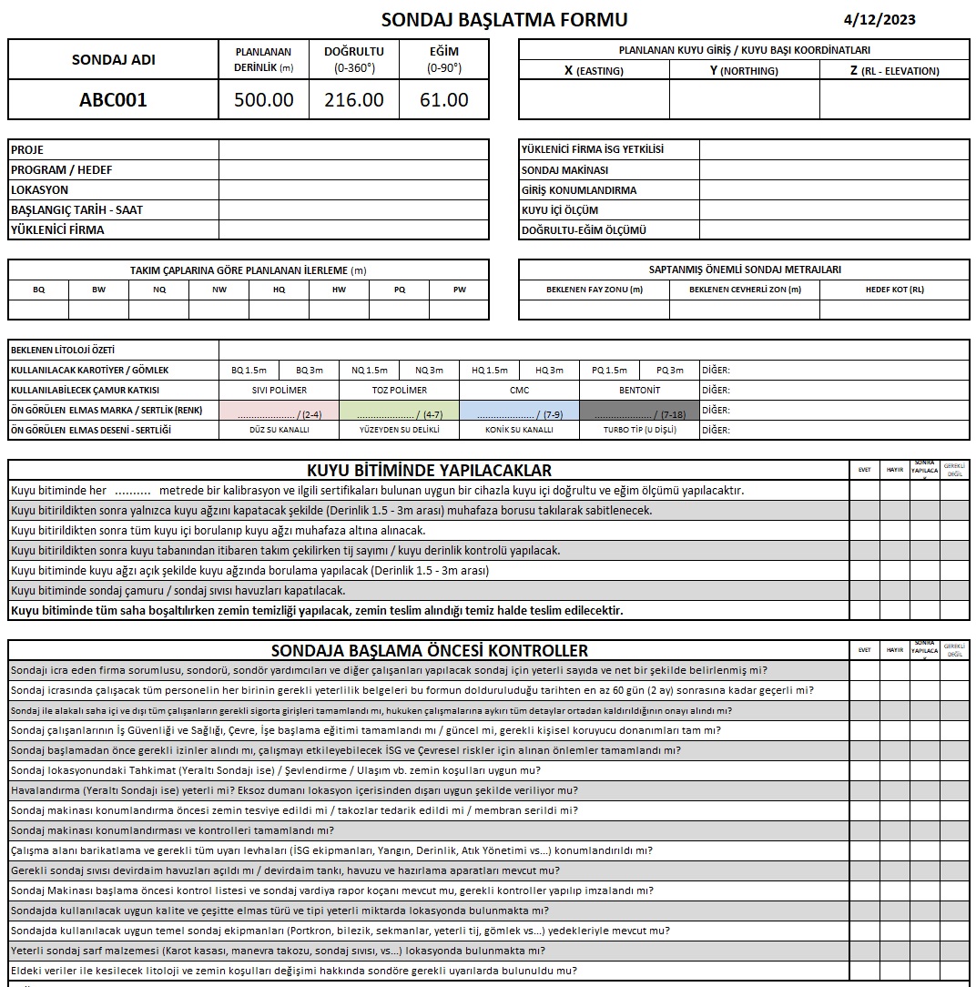
- Even if you record your drilling plans with a number, name your drillings in the order they are executed. For example, the last drilling started so far is the 2nd drilling (ABC002), you named the next plan you will start as 5 and started it, give the name of this drilling you started according to the order of execution, that is, “ABC003”.
- It will be very useful to have your drilling plans marked on the field and to have prepared the positioning and plan data that you have written on the side in a form when you go to position the drilling machine and “direct the drilling” before starting the drilling. This form, which you can give names similar to the well initiation form, will add order and extra seriousness to your work. Because you need to share it with the driller during the well progress and require attention during the progress; You can enter your instructions on many issues such as possible ore cutting meters, plan quantity, possible fault crossing intervals, etc. on these forms and record your communication with the driller or contractor company with a signature.
- Drillhole planning and turning these plans into programs is a job that requires experience and coordination. This critical process, which the ancients carried out with trigonometric calculations and cross-sections, has now become more accurate in 3D computer softwares and a job that is more mastered by geologist. Although it seems like a workflow, many dynamic factors affect the functioning.
- Although drilling plans cannot achieve absolute positive results at every start, they can sometimes detect very large mineralizations with determination. Sometimes, on the contrary, plans that initially show positive values may later indicate that mineralization is insufficient. Sometimes faults can slip’n slide the ore body you expect into places you don’t know about. We need to underline the importance of geologist experience in planning.
Subjects discussed in this article may overlap with your mineral exploration, modeling, mining operation and business development issues and may provide solutions for those. However, remember that various factors specific to your business may bring about different challenges. Therefore, seek support from expert consultants to evaluate all data together in order to convert potential into profit most efficiently.
Should you have any questions regarding the articles or consulting services, please don’t hesitate to get in touch with us.

GMRTC Mineral Exploration & Modeling & Operation Consultancy
Istanbul - Izmir - TÜRKİYE
SITE MAP
CONTACT US
Before quoting or copying from our site, you can contact info@gmrtc.com
All elements (texts, comments, videos, images) on the GMRTC website (www.gmrtc.com) are the property of GMRTC unless otherwise stated, and are published to provide insights to interested investors, professionals, and students. Any detail that may arise during your process will affect the subject matter you are interested in on this website; therefore, GMRTC (www.gmrtc.com) is not liable for any damages incurred. It is recommended that you consult experts with all your data before making any decisions based on the information provided.

